
Core: ESP32 1.0
Core: ESP32 1.0 datasheet — MCU, interfaces, I²C map, controls, sensors, and connectors.
Datasheet for Core: ESP32 1.0, the Attaky host module. For the user guide, see the Core: ESP32 manual. System-wide pin maps and the global I²C address table are on Frame & Connections.

Features
- ESP32-S3 MCU module with Wi-Fi and Bluetooth 5 LE
- 2.0-inch 240×320 color TFT with capacitive touch
- Five front keys (four direction keys + enter) down the right side, and four top buttons (L1, boot, power, R1)
- 6-axis IMU and an ambient-light sensor
- RGB status LED
- USB-C — the everyday charging port for the battery, plus flashing and serial via an onboard USB-to-UART bridge
Components
| Part | Role | Interface |
|---|---|---|
| ESP32-S3-WROOM-1U-N16R8 | MCU module (ESP32-S3) | — |
| CH340X | USB-to-UART bridge | USB 2.0 / UART |
| STK3311-X | Ambient-light + proximity sensor | I²C 0x48 |
| QMI8658A | 6-axis IMU (accel + gyro) | I²C 0x6B |
| AW9523BTQR | GPIO expander — peripheral interrupts | I²C 0x58 |
| AW9523BTQR | GPIO expander — buttons, RGB LED, touch reset | I²C 0x59 |
| ST7789 | 240×320 TFT display controller | SPI |
| FT6636 | Capacitive touch controller | I²C 0x38 |
Specifications
| Item | Value |
|---|---|
| MCU module | ESP32-S3-WROOM-1U-N16R8 |
| Core | Xtensa dual-core 32-bit LX7, up to 240 MHz |
| Flash | 16 MB (QuadSPI) |
| PSRAM | 8 MB (OctalSPI) |
| Wireless | Wi-Fi 2.4 GHz + Bluetooth 5 LE |
| Display | ST7789, 2.0-inch 240×320 RGB, SPI |
| Touch | FT6636 capacitive, I²C |
Display & touch
- Display: ST7789, 2.0-inch 240×320 RGB over SPI. The panel is mounted rotated 180° relative to the controller's default orientation; firmware applies a landscape-with-flip rotation so the image reads upright.
- Touch: FT6636 capacitive controller, I²C
0x38. Reset is driven by expander0x59pin P13 (active-low); the touch interrupt is routed through expander0x58pin P04.
I²C address map (on-board)
| Address | Device |
|---|---|
0x38 | FT6636 capacitive touch |
0x48 | STK3311-X ambient-light sensor |
0x58 | AW9523BTQR GPIO expander (interrupts) |
0x59 | AW9523BTQR GPIO expander (buttons / RGB LED / touch reset) |
0x6B | QMI8658A 6-axis IMU |
Controls
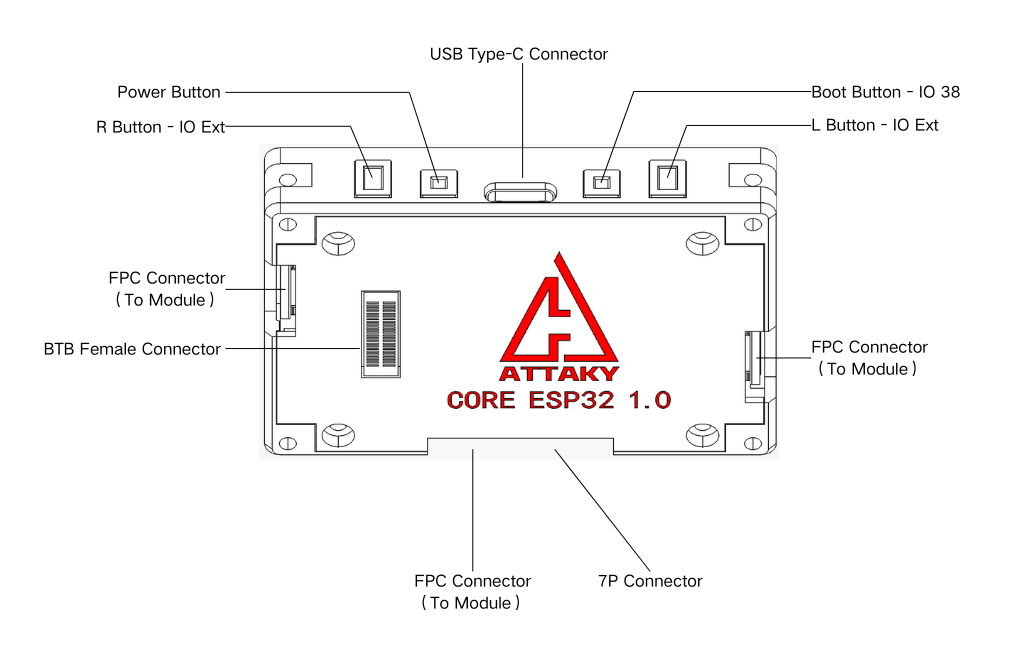
Five front keys — four direction keys and an enter key — in a vertical column on the right
side, and four buttons across the top edge: L1, boot, power, and R1 (left to right). All
buttons are active-low. Every button is read through the 0x59 GPIO expander except boot,
which is wired directly to the MCU.
| Button | Read via | Pin |
|---|---|---|
| Up | AW9523BTQR @ 0x59 | P04 |
| Down | AW9523BTQR @ 0x59 | P00 |
| Left | AW9523BTQR @ 0x59 | P01 |
| Right | AW9523BTQR @ 0x59 | P03 |
| Enter | AW9523BTQR @ 0x59 | P02 |
| L1 (top) | AW9523BTQR @ 0x59 | P05 |
| Boot (top) | ESP32-S3 (direct) | IO38 |
| Power (top) | AW9523BTQR @ 0x59 | P07 |
| R1 (top) | AW9523BTQR @ 0x59 | P06 |
- POWER is a hardware power switch. A long press (typically ≥ 2 s) toggles the device on
or off through the power path; firmware cannot intercept or redefine it. A short press is
readable by firmware as a normal key event on
0x59P07.
Sensors
- IMU — QMI8658A (I²C
0x6B), 6-axis accelerometer + gyroscope. The reference orientation (POSITION_A) is the device standing on a long edge, board vertical, with the sensor's +Y axis up. Axis mapping and gravity direction are consistent unit-to-unit, so orientation classification needs no calibration; absolute magnitude carries the sensor's factory tolerance (±6 % on the accelerometer), so sub-1° tilt accuracy requires a per-unit six-position calibration. - Ambient light — STK3311-X (I²C
0x48), 16-bit, used for display auto-brightness.
Status LED
RGB status LED, common-anode and active-low, driven by expander 0x59 pins P10 (red),
P11 (green), and P12 (blue).
USB
USB-C through the CH340X USB-to-UART bridge — used for firmware flashing and the serial console. It is also the everyday charging port: power over USB-C charges the battery in the attached Power module, and the device can keep running while it charges.
Connectors & power
Core attaches to the Frame through:

| Connector | Location |
|---|---|
| 50-pin board-to-board (BTB) | Back |
| 12-pin FPC | Left, right, and bottom (one each) |
| 7-pin power | Bottom |
Supply rails carried across the connectors: +3V3, VBAT 4.2 V, 5 V system, and USB 5 V.
For the complete connector pin map (every BTB / FPC / PIN position) and the system-wide I²C table, see Frame & Connections.
Mechanical
| Item | Value |
|---|---|
| Module body | 66 × 46 mm |
| Thickness | 12 mm |


Operating conditions
| Item | Value |
|---|---|
| Operating temperature | 0–40 °C (32–104 °F) |
| Water resistance | None — not waterproof, no IP rating |
Keep it dry, out of direct sunlight, and away from prolonged heat — do not leave it in a parked car.