
Control: Gamepad (Bottom) 1.0
Control: Gamepad (Bottom) 1.0 datasheet — buttons, button-to-pin map, I²C map, status LEDs, and connectors.
Datasheet for Control: Gamepad (Bottom) 1.0, the Attaky game-controller module. For the user guide, see the Control: Gamepad (Bottom) manual. System-wide pin maps and the global I²C address table are on Frame & Connections.


Features
- A direction pad, four action buttons (A/B/X/Y), four shoulder buttons (L1/L2/R1/R2), and four function buttons, across two halves
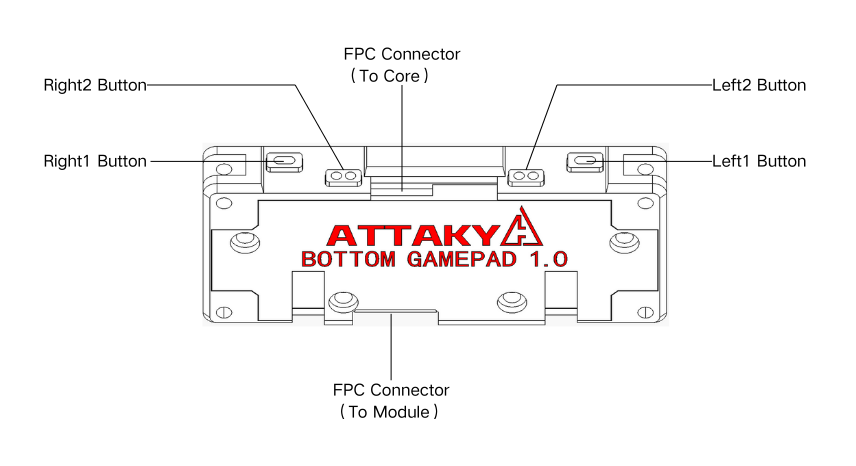
- L1/L2/R1/R2 each have a top button and a front button (wired in parallel) so they stay reachable when a module stacks over the top
- All buttons read through two I²C GPIO expanders, one per half (left
0x22, right0x26) - A per-half RGB status LED
- A separate active-low interrupt line per half — a press wakes the host before it scans
- Two 12-pin FPC connectors: UP to the Core, DOWN passes the bus straight through to chain a second Bottom Control module
Components
| Part | Role | Interface |
|---|---|---|
| TCA9555RTWR | GPIO expander — left buttons + RGB LED | I²C 0x22 |
| TCA9555RTWR | GPIO expander — right buttons + RGB LED | I²C 0x26 |
Specifications
| Item | Value |
|---|---|
| Buttons | 16 functions (D-pad, A/B/X/Y, L1/L2/R1/R2, four function keys); L1/L2/R1/R2 each have a top + front button (20 physical) |
| Button read | 2× TCA9555RTWR I²C GPIO expander, internal pull-ups, active-low |
| I²C bus | 400 kHz, shared by both expanders, addressed 0x22 / 0x26 |
| Interrupts | Two active-low lines, one per half (left / right) |
| Status LED | Two RGB LEDs (one per expander), active-low |
| Connectors | 2× 12-pin FPC (UP to Core, DOWN passthrough) |
I²C address map (on-board)
| Address | Device |
|---|---|
0x22 | TCA9555RTWR GPIO expander (left half — buttons / RGB LED) |
0x26 | TCA9555RTWR GPIO expander (right half — buttons / RGB LED) |
Both expanders share one I²C bus and are distinguished by slave address. The bus and each expander's interrupt land on the UP FPC — see the connector map under Connectors & power.
Controls
All buttons are active-low with internal pull-ups. The left half is read through the 0x22
expander, the right half through 0x26.
The four shoulder buttons (L1, L2, R1, R2) each have two physical buttons wired in parallel to the same pin — one on the top edge and one on the front face. When the gamepad is stacked into a build, the top buttons are covered, so the front buttons keep L1/L2/R1/R2 reachable; either one reads as the same input.
| Button | Read via | Pin |
|---|---|---|
| Up | TCA9555RTWR @ 0x22 | P05 |
| Down | TCA9555RTWR @ 0x22 | P02 |
| Left | TCA9555RTWR @ 0x22 | P04 |
| Right | TCA9555RTWR @ 0x22 | P03 |
| L1 (top + front) | TCA9555RTWR @ 0x22 | P06 |
| L2 (top + front) | TCA9555RTWR @ 0x22 | P07 |
| FN_L1 | TCA9555RTWR @ 0x22 | P00 |
| FN_L2 | TCA9555RTWR @ 0x22 | P01 |
| A | TCA9555RTWR @ 0x26 | P03 |
| B | TCA9555RTWR @ 0x26 | P04 |
| X | TCA9555RTWR @ 0x26 | P02 |
| Y | TCA9555RTWR @ 0x26 | P05 |
| R1 (top + front) | TCA9555RTWR @ 0x26 | P01 |
| R2 (top + front) | TCA9555RTWR @ 0x26 | P00 |
| FN_R1 | TCA9555RTWR @ 0x26 | P07 |
| FN_R2 | TCA9555RTWR @ 0x26 | P06 |
- Interrupts — each half has its own active-low
INT#. Either line pulls low when any button on that half is pressed, so the host scans only after an interrupt. Each line's FPC position is in the connector map under Connectors & power.
Status LEDs
Two RGB status LEDs, one driven by each expander, active-low (a low output lights the channel).
| Channel | Left @ 0x22 | Right @ 0x26 |
|---|---|---|
| Red | P17 | P17 |
| Green | P16 | P16 |
| Blue | P15 | P15 |
Connectors & power
Gamepad attaches and chains through two 12-pin FPC connectors (both AFC07-S12FCA-00):

| Connector | Location | Role |
|---|---|---|
| UP FPC | Top edge | To the Core (any Control FPC slot) |
| DOWN FPC | Bottom edge | Passthrough to a second Bottom Control module |
Each expander's own pins land on the UP FPC. The two expanders share the I²C bus (SCL / SDA) but each carries its own interrupt:
| Chip | Pin | Connector |
|---|---|---|
TCA9555RTWR @ 0x22 (left) | SCL | M-FPC9 (up) |
TCA9555RTWR @ 0x22 (left) | SDA | M-FPC10 (up) |
TCA9555RTWR @ 0x22 (left) | INT# (L_INT) | M-FPC8 (up) |
TCA9555RTWR @ 0x26 (right) | SCL | M-FPC9 (up) |
TCA9555RTWR @ 0x26 (right) | SDA | M-FPC10 (up) |
TCA9555RTWR @ 0x26 (right) | INT# (R_INT) | M-FPC7 (up) |
SCL (M-FPC9) and SDA (M-FPC10) are one shared I²C bus tapped by both expanders, which
are told apart by slave address; INT# is separate per half (M-FPC8 left, M-FPC7 right).
Supply rails — carried on the UP FPC alongside the bus: +3V3, 5 V system, and GND. These are board power, not chip signals.
DOWN FPC (passthrough) — the DOWN connector carries the full 12-line bus straight through from the UP FPC: the shared I²C bus, both interrupt lines, the host's spare control GPIO, and the supply rails (+3V3, 5 V system, GND). By design, a chained module sees the same M-FPC signals as if it attached to the Core directly. This module taps the shared I²C bus and its two interrupt lines on the passthrough without breaking it.
For the complete connector pin map (every FPC position) and the system-wide I²C table, see Frame & Connections.
Mechanical
| Item | Value |
|---|---|
| Module body | 66 × 28 mm |
| Thickness | 9.5 mm |


Operating conditions
| Item | Value |
|---|---|
| Operating temperature | 0–40 °C (32–104 °F) |
| Water resistance | None — not waterproof, no IP rating |
Keep it dry, out of direct sunlight, and away from prolonged heat — do not leave it in a parked car.