
Control: Keyboard (Bottom) 1.0
Control: Keyboard (Bottom) 1.0 datasheet — QWERTY key matrix, controllers, I²C map, status LEDs, and connectors.
Datasheet for Control: Keyboard (Bottom) 1.0, the Attaky bottom-edge QWERTY keyboard. For the user guide, see the Keyboard (Bottom) manual. System-wide pin maps and the global I²C address table are on Frame & Connections.
Features
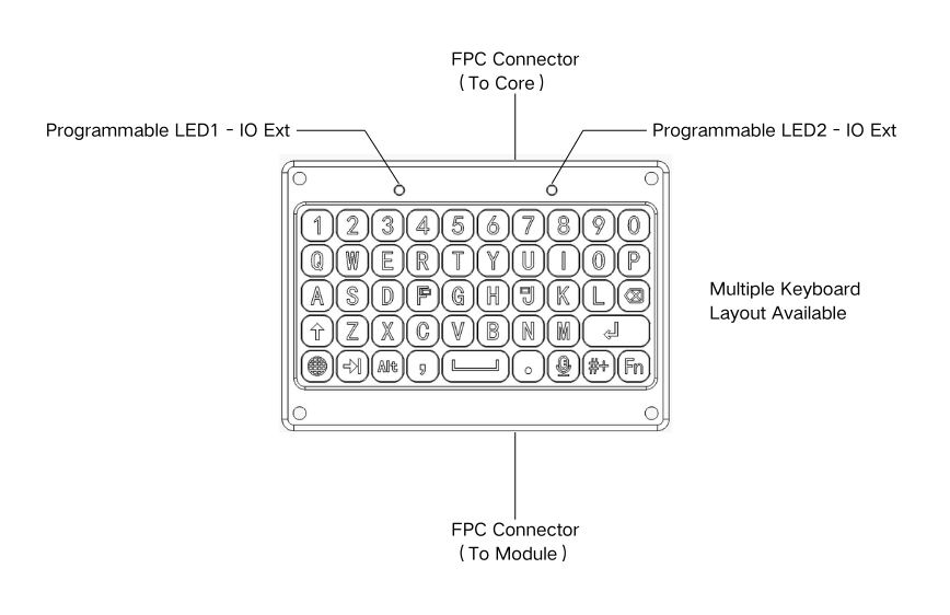
- Physical QWERTY keyboard, 48 keys — one integrated unit, electrically split into a left and a right scan zone
- Each zone is a 5×5 key matrix scanned by its own GPIO expander
- Letters, numbers, common punctuation, and modifier keys (Shift, Tab, Alt, language, Fn)
- One RGB status LED per zone, driven by the expander
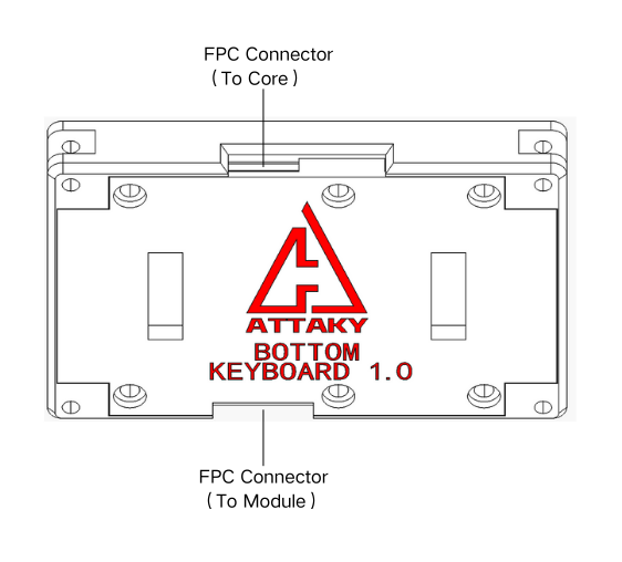
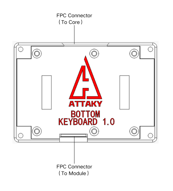
- Two FPC connectors: an UP cable to the Core and a DOWN cable that passes through to a second bottom Control module
Components
| Part | Role | Interface |
|---|---|---|
| AW9523BTQR | GPIO expander — left zone: 5×5 matrix scan + RGB LED | I²C 0x5A |
| AW9523BTQR | GPIO expander — right zone: 5×5 matrix scan + RGB LED | I²C 0x5B |
Specifications
| Item | Value |
|---|---|
| Layout | QWERTY, 48 keys, split left + right |
| Matrix | Two 5×5 matrices (one per zone) |
| Controllers | 2 × AW9523BTQR GPIO expanders |
| Interface | I²C, up to 400 kHz |
| Status LEDs | One RGB LED per zone |
| Interrupts | Separate active-low INT per zone (L_INT, R_INT) |
| Connectors | 2 × 12-pin FPC (UP to Core, DOWN passthrough) |
I²C address map (on-board)
| Address | Device |
|---|---|
0x5A | AW9523BTQR GPIO expander (left zone — matrix + RGB LED) |
0x5B | AW9523BTQR GPIO expander (right zone — matrix + RGB LED) |
Both expanders share the keyboard's I²C bus and are distinguished by their slave addresses
(set by AD0/AD1 strapping). This bus is the same one the Core uses for its on-board devices,
so 0x5A/0x5B are reserved for the keyboard system-wide.
Controls
The keyboard is a single physical unit, divided electrically into two scan zones (left and right), each with its own GPIO expander. Each zone is a 5×5 key matrix: the expander drives one matrix row low at a time (pins P10–P14) and reads the five columns (pins P00–P04); a key reads as pressed when its row × column intersection pulls a column low. All keys are active-low. The matrix rows are ROW0–ROW4 and the columns are COL0–COL4.
Left zone — AW9523BTQR @ 0x5A
| Key | Read via | Pin (row × col) |
|---|---|---|
| 1 | AW9523BTQR @ 0x5A | ROW0 (P10) × COL0 (P00) |
| 2 | AW9523BTQR @ 0x5A | ROW0 (P10) × COL1 (P01) |
| 3 | AW9523BTQR @ 0x5A | ROW0 (P10) × COL2 (P02) |
| 4 | AW9523BTQR @ 0x5A | ROW0 (P10) × COL3 (P03) |
| 5 | AW9523BTQR @ 0x5A | ROW0 (P10) × COL4 (P04) |
| Q | AW9523BTQR @ 0x5A | ROW1 (P11) × COL0 (P00) |
| W | AW9523BTQR @ 0x5A | ROW1 (P11) × COL1 (P01) |
| E | AW9523BTQR @ 0x5A | ROW1 (P11) × COL2 (P02) |
| R | AW9523BTQR @ 0x5A | ROW1 (P11) × COL3 (P03) |
| T | AW9523BTQR @ 0x5A | ROW1 (P11) × COL4 (P04) |
| A | AW9523BTQR @ 0x5A | ROW2 (P12) × COL0 (P00) |
| S | AW9523BTQR @ 0x5A | ROW2 (P12) × COL1 (P01) |
| D | AW9523BTQR @ 0x5A | ROW2 (P12) × COL2 (P02) |
| F | AW9523BTQR @ 0x5A | ROW2 (P12) × COL3 (P03) |
| G | AW9523BTQR @ 0x5A | ROW2 (P12) × COL4 (P04) |
| Shift | AW9523BTQR @ 0x5A | ROW3 (P13) × COL0 (P00) |
| Z | AW9523BTQR @ 0x5A | ROW3 (P13) × COL1 (P01) |
| X | AW9523BTQR @ 0x5A | ROW3 (P13) × COL2 (P02) |
| C | AW9523BTQR @ 0x5A | ROW3 (P13) × COL3 (P03) |
| V | AW9523BTQR @ 0x5A | ROW3 (P13) × COL4 (P04) |
| Language | AW9523BTQR @ 0x5A | ROW4 (P14) × COL0 (P00) |
| Tab | AW9523BTQR @ 0x5A | ROW4 (P14) × COL1 (P01) |
| Alt | AW9523BTQR @ 0x5A | ROW4 (P14) × COL2 (P02) |
| , (comma) | AW9523BTQR @ 0x5A | ROW4 (P14) × COL3 (P03) |
| Space | AW9523BTQR @ 0x5A | ROW4 (P14) × COL4 (P04) |
Right zone — AW9523BTQR @ 0x5B
| Key | Read via | Pin (row × col) |
|---|---|---|
| 6 | AW9523BTQR @ 0x5B | ROW0 (P10) × COL0 (P00) |
| 7 | AW9523BTQR @ 0x5B | ROW0 (P10) × COL1 (P01) |
| 8 | AW9523BTQR @ 0x5B | ROW0 (P10) × COL2 (P02) |
| 9 | AW9523BTQR @ 0x5B | ROW0 (P10) × COL3 (P03) |
| 0 | AW9523BTQR @ 0x5B | ROW0 (P10) × COL4 (P04) |
| Y | AW9523BTQR @ 0x5B | ROW1 (P11) × COL0 (P00) |
| U | AW9523BTQR @ 0x5B | ROW1 (P11) × COL1 (P01) |
| I | AW9523BTQR @ 0x5B | ROW1 (P11) × COL2 (P02) |
| O | AW9523BTQR @ 0x5B | ROW1 (P11) × COL3 (P03) |
| P | AW9523BTQR @ 0x5B | ROW1 (P11) × COL4 (P04) |
| H | AW9523BTQR @ 0x5B | ROW2 (P12) × COL0 (P00) |
| J | AW9523BTQR @ 0x5B | ROW2 (P12) × COL1 (P01) |
| K | AW9523BTQR @ 0x5B | ROW2 (P12) × COL2 (P02) |
| L | AW9523BTQR @ 0x5B | ROW2 (P12) × COL3 (P03) |
| Delete | AW9523BTQR @ 0x5B | ROW2 (P12) × COL4 (P04) |
| B | AW9523BTQR @ 0x5B | ROW3 (P13) × COL0 (P00) |
| N | AW9523BTQR @ 0x5B | ROW3 (P13) × COL1 (P01) |
| M | AW9523BTQR @ 0x5B | ROW3 (P13) × COL2 (P02) |
| Enter | AW9523BTQR @ 0x5B | ROW3 (P13) × COL4 (P04) |
| . (period) | AW9523BTQR @ 0x5B | ROW4 (P14) × COL1 (P01) |
| Mic | AW9523BTQR @ 0x5B | ROW4 (P14) × COL2 (P02) |
| # | AW9523BTQR @ 0x5B | ROW4 (P14) × COL3 (P03) |
| Fn | AW9523BTQR @ 0x5B | ROW4 (P14) × COL4 (P04) |
The right zone uses a 5×5 grid; two grid positions (ROW3 × COL3 and ROW4 × COL0) are routed but carry no physical key, so this zone has 23 keys (the left zone has 25, for 48 total).
When any key is pressed, the zone's expander pulls its interrupt line low — left zone on L_INT, right zone on R_INT — see the connector map under Connectors & power. Each zone can be scanned independently.
Status LEDs
One RGB LED per zone, driven by the same expander as that zone's matrix:
| Zone | Driven by | Pins |
|---|---|---|
| Left | AW9523BTQR @ 0x5A | P17 (red), P16 (green), P15 (blue) |
| Right | AW9523BTQR @ 0x5B | P17 (red), P16 (green), P15 (blue) |
The LEDs are active-low (pin low = lit).
Connectors & power
The keyboard chains through two 12-pin FPC connectors: an UP cable to the Core and a DOWN cable that passes through to a second bottom Control module. Only the two expanders' bus and interrupt pins land on the connector; the matrix and RGB pins (P00–P17) stay internal to the module (see Controls and Status LEDs). Each expander pin lands on an UP-FPC position:

| Chip | Pin | Connector |
|---|---|---|
AW9523BTQR @ 0x5A (left) | SCL | M-FPC9 (up) |
AW9523BTQR @ 0x5A (left) | SDA | M-FPC10 (up) |
AW9523BTQR @ 0x5A (left) | INTN | M-FPC5 (up) |
AW9523BTQR @ 0x5B (right) | SCL | M-FPC9 (up) |
AW9523BTQR @ 0x5B (right) | SDA | M-FPC10 (up) |
AW9523BTQR @ 0x5B (right) | INTN | M-FPC7 (up) |
Both expanders share the one I²C bus (SCL on M-FPC9, SDA on M-FPC10) and are distinguished by slave address; the interrupts run on separate lines (left INTN on M-FPC5, right INTN on M-FPC7).
Supply rails
The FPC also carries the module power rails (shared across the UP and DOWN cables):
| Rail | Connector |
|---|---|
| +3V3 | M-FPC (up / down) |
| 5 V | M-FPC (up / down) |
| GND | M-FPC (up / down) |
DOWN FPC (passthrough)
The DOWN connector is a straight passthrough of all 12 lines — the same I²C SCL/SDA, the L_INT/R_INT interrupt lines, spare GPIO, and the +3V3 / 5 V / GND rails the UP cable carries — so a second Control module (such as a gamepad) can stack below the keyboard on the same chain. The keyboard's two expanders tap that shared bus without breaking the passthrough. The current bottom-Control chain length is two modules. This signal passthrough is guaranteed by design, so a chained module is electrically indistinguishable from one attached to the Core directly.
For the complete connector pin map (every FPC position) and the system-wide I²C table, see Frame & Connections.
Mechanical
| Item | Value |
|---|---|
| Module body | 66 × 46 mm |
| Thickness | 9.5 mm |


Operating conditions
| Item | Value |
|---|---|
| Operating temperature | 0–40 °C (32–104 °F) |
| Water resistance | None — not waterproof, no IP rating |
Keep it dry, out of direct sunlight, and away from prolonged heat — do not leave it in a parked car.