
Power: Standard Cell 1.0
Power: Standard Cell 1.0 datasheet — battery, fuel gauge, I²C map, connectors, and power rails.
Datasheet for Power: Standard Cell 1.0, the Attaky rechargeable battery module. For the user guide, see the Power: Standard Cell manual. System-wide pin maps and the global I²C address table are on Frame & Connections.

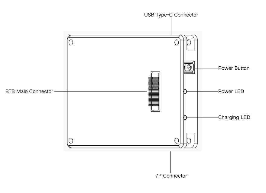
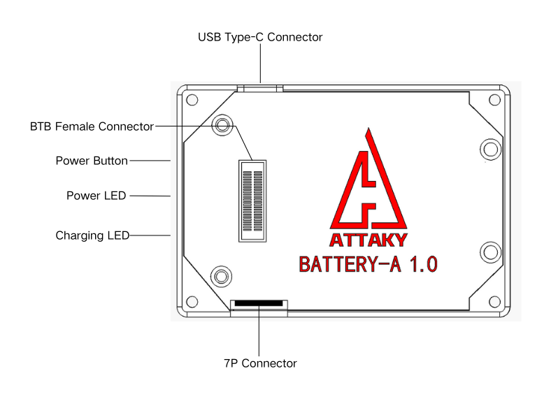
Features
- Single-cell rechargeable lithium-ion battery module, 1000 mAh — no firmware
- MAX17048 micro-power battery fuel gauge, read over I²C (state-of-charge, voltage, rate)
- Charges over the Core's USB-C in use, or an on-module USB-C port when standalone / Core off
- On-edge power button and power / charging indicator LEDs
- Two supply paths: 5 V and 4.2 V rails carried to the Core
- Connects to the Core by either a 50-pin board-to-board connector or a 7-pin harness (pick one)
- Rear 50-pin board-to-board connector passes every signal through so an Expand module can stack on top
Components
| Part | Role | Interface |
|---|---|---|
| MAX17048G+T10 | Single-cell Li-ion fuel gauge (state-of-charge / voltage / rate) | I²C 0x36 |
Specifications
| Item | Value |
|---|---|
| Battery | Single-cell (1S) rechargeable lithium-ion |
| Capacity | 1000 mAh |
| Fuel gauge | MAX17048G+T10, I²C 0x36 |
| Fuel-gauge bus speed | 400 kHz |
| Fuel-gauge quiescent current | 3 µA |
| Supply rails | 4.2 V (VBAT) and 5 V system |
| Charging | Core's USB-C in use; on-module USB-C when standalone or Core off |
| Firmware | None (power module) |
Charging
The cell charges over USB-C through one of two ports:
- Core USB-C — the everyday path. With the Power module assembled in a build, charge through the Core's USB-C; the device can keep running while it charges.
- On-module USB-C — a convenience port on the battery module itself, for charging the cell on its own. It works only when the module is standalone (detached from a build) or when the Core is powered off. In normal assembled use with the Core on, charge through the Core instead.
I²C address map (on-board)
| Address | Device |
|---|---|
0x36 | MAX17048G+T10 fuel gauge |
Connectors & power
Power: Standard Cell carries three board-to-board / harness connectors:


| Connector | Location | Role |
|---|---|---|
| 50-pin board-to-board (M-BTB) | Front | Attaches to the Core's rear connector (one of two paths to the Core) |
| 7-pin harness (SH1.0-7P) | Bottom edge | Harness to the Core's bottom 7-pin connector (one of two paths to the Core) |
| 50-pin board-to-board (F-BTB) | Rear | Pass-through for a stacked Expand module |
The front 50-pin connector and the 7-pin harness are the two alternative paths to the Core — use one or the other, not both. Both paths share the same MAX17048 fuel gauge.
The rear 50-pin connector passes every signal from the front connector straight through, so
an Expand module seated on the rear sees the same pins it would see attached directly to the
Core — forming a Core ← Power ← Expand stack. Internally, a few lines are tapped in
parallel for the fuel gauge's alert and the battery / 5 V rails; the tap does not break the
pass-through. The rear pass-through applies only when the module is attached over the front
board-to-board path.
The only chip on the module is the MAX17048 fuel gauge. The front board-to-board connector and the 7-pin harness are two alternative paths to the Core; each gauge pin sits at a position on both (use whichever path is in service):
| Pin | Front BTB | 7-pin harness |
|---|---|---|
| SCL | M-BTB47 | M-PIN6 |
| SDA | M-BTB46 | M-PIN5 |
| ALRT# | M-BTB19 | M-PIN7 |
Supply rails (battery and system power, not chip pins) carried to the Core:
| Rail | Value |
|---|---|
| VBAT | 4.2 V battery rail |
| 5 V system | 5 V boosted system rail |
For the complete connector pin map (every BTB / PIN position) and the system-wide I²C table, see Frame & Connections.
Mechanical
| Item | Value |
|---|---|
| Module body | 66 × 46 mm |
| Thickness | 10 mm |


Operating conditions
| Item | Value |
|---|---|
| Operating temperature | 0–40 °C (32–104 °F) |
| Water resistance | None — not waterproof, no IP rating |
Keep it dry, out of direct sunlight, and away from prolonged heat — do not leave it in a parked car.